
Your AC suddenly stops cooling on the hottest day of summer, leaving you sweating and frustrated. Before you panic about expensive repairs, the culprit might be a small but critical component that costs less than a dinner out.
The HVAC low pressure switch is a safety device that protects your compressor by monitoring refrigerant pressure and shutting down the system when pressure drops below safe operating levels, typically between 25-40 PSI. This automatic guardian prevents catastrophic compressor damage that could cost thousands to repair.
This comprehensive guide covers everything from basic operation to advanced troubleshooting techniques used by HVAC professionals. You’ll learn how to identify, test, and replace this crucial component while understanding the warning signs that demand immediate attention.
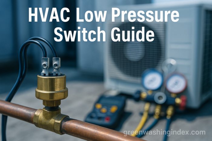
An HVAC low pressure switch is an electrical safety control that monitors the refrigerant pressure on the suction side of your air conditioning system. When pressure drops below a predetermined threshold, this switch opens the electrical circuit to the compressor, preventing operation until safe pressure levels return.
The switch contains a pressure-sensitive diaphragm connected to electrical contacts. As system pressure changes, the diaphragm moves, either opening or closing the circuit based on preset pressure settings.
Low refrigerant pressure creates a dangerous condition called “slugging” where liquid refrigerant returns to the compressor instead of vapor. This liquid can’t be compressed and causes severe mechanical damage to compressor valves and pistons.
The pressure switch acts as your system’s first line of defense by shutting down operation before damage occurs. Without this protection, a simple refrigerant leak could destroy your entire compressor within hours of operation.
Modern HVAC systems rely on these switches to maintain optimal performance while preventing the need for costly air conditioner maintenance emergencies.
Most residential HVAC low pressure switches feature automatic reset functionality. When system pressure returns to normal levels (typically 65-80 PSI), the switch automatically closes and allows normal operation to resume.
Manual reset switches require physical intervention to restore operation after a fault condition. These are less common in residential applications but provide an extra safety layer by forcing technicians to investigate the cause before restarting.
Some advanced systems use electronic pressure transducers instead of mechanical switches. These provide precise pressure readings to the control board and enable more sophisticated diagnostic capabilities.
The internal mechanism consists of several critical components working in harmony:
Understanding the distinction between these two safety devices is crucial for proper HVAC diagnostics:
| Switch Type | Cut-Out Pressure | Cut-In Pressure | Normal Operating Range |
|---|---|---|---|
| Low Pressure | 25-40 PSI | 65-80 PSI | 90-110 PSI |
| High Pressure | 400-450 PSI | 300-350 PSI | 250-350 PSI |
These pressure ranges vary slightly based on refrigerant type and system design, but the fundamental difference remains constant.
Low pressure switches mount on the larger suction line between the evaporator and compressor. This line feels cool to the touch during operation and typically has insulation.
High pressure switches install on the smaller liquid line leaving the compressor. This line feels warm or hot during operation and connects to the condenser coil.
The reset mechanism represents the most significant operational difference between these switches. Low pressure switches typically reset automatically when pressure normalizes, minimizing service calls for temporary conditions.
High pressure switches often require manual reset to ensure technicians investigate the cause. High pressure conditions indicate serious problems like blocked condenser coils or failed fan motors that need immediate attention.
Low pressure switches respond to conditions that reduce system refrigerant pressure below safe levels. Common triggers include refrigerant leaks, iced evaporator coils, or restricted airflow.
High pressure switches activate when discharge pressure exceeds safe limits. This occurs with dirty condenser coils, failed condenser fans, or overcharged systems.
Both switches work together to create a comprehensive safety net for your HVAC investment.
Professional HVAC technicians rely on specific pressure parameters when diagnosing system problems. The sweet spot for most residential systems falls between 90-110 PSI on the low side during normal cooling operation.
These pressures correlate directly with refrigerant temperature and system efficiency. When outdoor temperatures reach 90°F, expect low-side pressures around 70 PSI for R-410A systems.
Pressure readings outside normal ranges indicate underlying issues requiring immediate attention. Regular monitoring helps identify problems before they escalate into major repairs.
The cut-out setting determines when your system shuts down for protection. Most residential switches cut out between 25-40 PSI, providing adequate safety margin before damage occurs.
Cut-in settings typically range from 65-80 PSI, ensuring sufficient refrigerant pressure before allowing restart. This differential prevents rapid cycling that could damage electrical components.
Factory settings work well for most applications, but extreme climates may require adjustment. Always consult manufacturer specifications before modifying these critical parameters.
HVAC pressure switches handle various electrical loads depending on system design:
These specifications ensure compatibility with both low-voltage control circuits and line-voltage applications.
Standard connection types include:
Proper fitting selection prevents leaks and ensures accurate pressure sensing. Always match replacement switches to your system’s connection type.
Locating your low pressure switch starts with identifying the suction line. This larger copper pipe runs from your indoor evaporator coil to the outdoor compressor unit.
The suction line feels cool during operation and usually features black foam insulation. Follow this line from where it exits your home to the outdoor unit.
Temperature difference provides the easiest identification method. While the system runs, the suction line remains noticeably cooler than the smaller liquid line.
Look for these visual cues when searching for your pressure switch:
The switch orientation varies by manufacturer, but most mount vertically for proper diaphragm operation.
Different HVAC configurations place switches in predictable locations:
Split Systems: Near the compressor on the suction line service valve Package Units: Inside the electrical compartment near the compressor Heat Pumps: May have two switches for heating and cooling modes Mini-Splits: Often integrated into the outdoor unit control board
Manufacturer service manuals provide exact locations for specific models.
Safety must be your top priority when working near HVAC equipment:
Never attempt to locate or test switches while the system operates. High voltage and moving parts create serious hazards.
The most obvious symptom of pressure switch failure appears as erratic system behavior. Your AC might start briefly, run for seconds or minutes, then shut down unexpectedly.
This short cycling pattern indicates the switch detects low pressure and protects the compressor. However, if pressure readings show normal levels, the switch itself has likely failed.
Continuous cycling stresses electrical components and wastes energy. Address this issue promptly to prevent secondary damage to contactors and capacitors.
A faulty low pressure switch creates distinct compressor symptoms that experienced technicians recognize immediately. The compressor might fail to start despite the thermostat calling for cooling.
Sometimes you’ll hear the contactor pull in, but the compressor remains silent. This indicates the pressure switch has interrupted the control circuit despite adequate refrigerant levels.
Intermittent operation poses diagnostic challenges. The compressor might run normally for hours, then suddenly stop without apparent cause.
Modern communicating thermostats display specific error messages for pressure switch faults:
These codes appear after the switch remains open for more than 5 seconds during a call for cooling. The system typically attempts restart 3-5 times before entering lockout mode.
Smart thermostats from brands like Nest or Ecobee may simply show “cooling disabled” without specific pressure switch indication.
Visual inspection reveals several failure indicators:
Corrosion: Green or white buildup on terminals indicates moisture intrusion Burn marks: Darkened areas suggest electrical arcing Oil residue: Refrigerant oil near the connection points to internal leaks Loose wires: Vibration can loosen terminal connections over time
Physical damage often accompanies electrical failure. Replace any switch showing these warning signs immediately.
Refrigerant leaks represent the leading cause of legitimate low pressure switch activation. Even small leaks gradually reduce system charge until pressure drops below the switch threshold.
Common leak locations include:
Annual leak checks during routine maintenance help identify problems before they trigger switch activation. This sustainable approach prevents refrigerant waste and protects the environment.
Ice formation on evaporator coils creates a pressure drop that triggers switch activation. This condition develops from several underlying issues:
Restricted airflow tops the list of freeze-causing conditions. Dirty filters block airflow, reducing heat transfer and dropping coil temperatures below freezing.
Blower motor problems contribute to freezing by reducing air movement across the coil. Worn bearings, loose belts, or electrical issues all impact blower performance.
Low refrigerant charge ironically causes freezing too. Reduced pressure lowers refrigerant temperature, creating ice that further restricts heat transfer.
Dirty air filters cause more AC failures than any other single factor. When filters clog with dust and debris, airflow drops dramatically across the evaporator coil.
Reduced airflow creates a cascade of problems:
Change filters monthly during peak cooling season. This simple maintenance task prevents most pressure switch activations and extends equipment life.
Several mechanical failures can trigger low pressure conditions:
TXV Failure: Thermostatic expansion valves regulate refrigerant flow. When stuck closed, they starve the evaporator and drop suction pressure.
Blocked Filter Drier: Moisture or debris in the filter drier restricts refrigerant flow, mimicking a low charge condition.
Compressor Valve Damage: Worn compressor valves reduce pumping capacity, lowering system pressures throughout.
These failures require professional diagnosis and repair beyond simple switch replacement.
Proper testing requires specific tools for accurate results:
Essential Tools:
Safety Equipment:
Never compromise on safety when working with electrical components.
Safety begins with proper power isolation:
Wait five minutes after power disconnection for capacitors to discharge before proceeding.
Configure your multimeter for accurate pressure switch testing:
With power OFF, disconnect wires from the pressure switch terminals. This isolates the switch for accurate testing.
Understanding multimeter readings determines switch condition:
Good Switch Indicators:
Failed Switch Indicators:
Document all readings for warranty claims or future reference.
Verify actual system pressures to confirm switch operation:
This comprehensive approach eliminates guesswork and confirms whether the switch or system pressure is the problem.
Several simple solutions might restore normal operation without switch replacement:
Tap Test: Gently tap the switch body with a screwdriver handle. Stuck diaphragms sometimes free themselves with light vibration.
Terminal Cleaning: Disconnect power and clean corroded terminals with electrical contact cleaner. Corrosion increases resistance and causes intermittent operation.
Wire Tightening: Check all connections for looseness. Vibration gradually loosens terminals, creating high-resistance connections.
These temporary fixes help diagnose whether replacement is necessary but shouldn’t substitute for proper repair.
Systematic connection testing reveals hidden problems:
Poor connections cause more failures than actual switch defects. Address wiring issues before condemning the switch.
Physical obstructions sometimes prevent proper switch operation:
Debris Removal: Inspect the pressure port for dirt or corrosion. Clean carefully with appropriate solvents.
Ice Clearing: If ice blocks the pressure port, allow natural thawing. Never use heat guns or torches near refrigerant components.
Tubing Inspection: Check capillary tubes for kinks or damage. Even small restrictions affect pressure sensing accuracy.
Professional cleaning might be necessary for severe blockages.
Confirm actual system pressures before replacing any components:
Static Pressure Test: With system off, pressures should equalize at outdoor temperature-dependent values Running Pressure Test: Monitor both high and low side pressures during operation Temperature Correlation: Use PT charts to verify pressure-temperature relationships
Abnormal pressures indicate system problems beyond switch failure. Address underlying issues to prevent repeated switch replacements.
Replace your pressure switch when:
Intermittent failures warrant immediate replacement to prevent unexpected breakdowns during extreme weather.
Match these specifications exactly:
Universal switches work for some applications but verify all specifications match your system requirements.
Follow this systematic approach for successful replacement:
Preparation Phase:
Removal Phase:
Installation Phase:
Never overtighten fittings, as this damages threads and causes leaks.
Comprehensive testing ensures proper installation:
Document installation date and switch specifications for future reference. This information proves valuable for warranty claims or troubleshooting.
Proactive maintenance dramatically extends switch life:
Monthly Tasks:
Annual Professional Service:
Following manufacturer maintenance schedules prevents most pressure-related failures.
Clean filters represent your first defense against pressure switch problems. Clogged filters cause more AC failures than any other factor.
Filter replacement frequency depends on several factors:
High-efficiency filters require more frequent changes due to increased restriction. Balance filtration needs with system airflow requirements.
Annual professional inspections identify problems before they cause failures:
Technician Checklist:
Professional service agreements often include priority service and repair discounts, providing peace of mind during peak season.
Recognizing early symptoms prevents emergency breakdowns:
Address these warnings promptly to avoid compressor damage and emergency repair costs.
Understanding cost structures helps budget for repairs:
| Service Type | DIY Cost | Professional Cost |
|---|---|---|
| Switch Only | $25-50 | $25-50 |
| Labor | $0 | $75-150 |
| Diagnostic Fee | $0 | $50-100 |
| Total Range | $25-50 | $150-300 |
DIY saves money but requires proper tools and knowledge. Mistakes can void warranties or cause additional damage.
Several variables influence final costs:
Location: Urban areas typically charge 20-30% more System Type: Commercial or specialized systems cost more Accessibility: Difficult locations increase labor time Emergency Service: After-hours calls double or triple rates Additional Repairs: Often other issues need attention
Request detailed estimates before authorizing work.
Delaying pressure switch replacement creates expensive consequences:
Investing $200 in timely replacement prevents thousands in consequential damages.
Professional technicians follow these proven methods:
Documentation: Record all pressure readings and switch settings Calibration: Verify switch accuracy annually Cleanliness: Keep electrical connections clean and dry Proper Tools: Use correct fitting wrenches to prevent damage System Approach: Consider entire system health, not just components
These practices extend equipment life and improve reliability.
Learn from these frequent DIY errors:
Each mistake can cause expensive damage or safety hazards.
Certain situations demand professional expertise:
Professional service ensures safety and protects your investment.
Understand warranty implications before attempting repairs:
Manufacturer Warranties: Often require professional installation Extended Warranties: May exclude DIY repairs Parts Warranties: Usually 1-2 years from installation Labor Warranties: Vary by contractor (30 days to 1 year)
Document all work performed to protect warranty coverage. Save receipts and service records for future claims.
Never bypass safety switches, even temporarily. Bypassing eliminates compressor protection and risks catastrophic failure within hours.
Running without pressure protection voids warranties and may violate local codes. The temporary comfort isn’t worth thousands in potential damage.
If your system needs cooling immediately, use portable units or fans while awaiting proper repair.
Pressure switches typically last 10-15 years with proper maintenance. However, several factors affect lifespan:
Replace switches showing any signs of failure rather than waiting for complete breakdown.
Repeated tripping indicates underlying system problems requiring investigation:
Most Common Causes:
Address root causes to prevent repeated switch replacements and system damage.
Ignoring switch problems creates a cascade of failures:
Immediate Effects: Reduced cooling capacity and comfort Short-term Damage: Compressor overheating and oil breakdown Long-term Consequences: Complete compressor failure requiring replacement Financial Impact: $1,500-4,000 for compressor replacement vs $200 for switch
Early intervention saves money and prevents system downtime.
Yes, a malfunctioning switch can destroy your compressor in two ways:
Fails Closed: Allows operation with insufficient refrigerant, causing overheating Fails Open: Creates excessive cycling, stressing electrical components
Both failure modes cause premature wear and eventual compressor failure. This explains why timely replacement is crucial for system longevity.
The HVAC low pressure switch serves as your system’s silent guardian, protecting your valuable compressor from damage due to low refrigerant conditions. Understanding its operation, recognizing failure symptoms, and maintaining proper system pressures ensures reliable cooling when you need it most.
Regular maintenance, including filter changes and annual professional inspections, prevents most pressure switch problems. When issues arise, proper testing procedures distinguish between switch failure and underlying system problems.
Whether you choose DIY replacement or professional service, addressing pressure switch issues promptly protects your investment and maintains home comfort. Schedule your annual HVAC inspection today to ensure your system’s safety devices function properly before peak cooling season arrives.
Don't let aphids, slugs, and caterpillars ruin another plant. Take back control with simple, natural methods that actually work.