
I recently helped my neighbor install a smart thermostat, and we discovered his heating bills dropped by $180 that winter. That experience taught me that proper thermostat wiring isn’t just about making your HVAC system work – it’s about maximizing energy efficiency and reducing your carbon footprint.
With smart thermostats potentially saving homeowners 8% on heating and cooling bills (that’s about $50 annually for the average household), understanding thermostat wiring has become more valuable than ever. The Environmental Protection Agency estimates that if every American home upgraded to an Energy Star certified smart thermostat, we’d prevent 13 billion pounds of greenhouse gas emissions annually – equivalent to taking 1.2 million cars off the road.
In this guide, I’ll walk you through everything you need to know about thermostat wiring, from basic wire identification to advanced smart thermostat installation. Whether you’re upgrading to an energy-efficient model or troubleshooting your current system, you’ll find practical, safety-first instructions that work for both beginners and experienced DIYers.
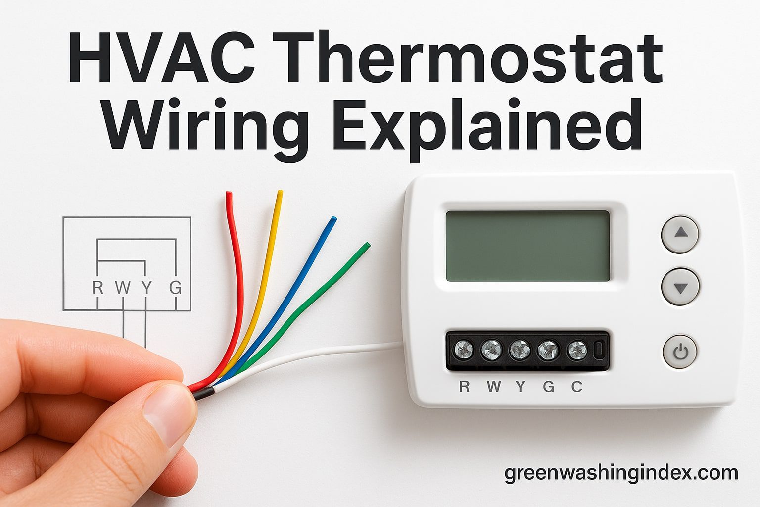
Before we dive into the actual wiring process, let’s understand what we’re working with. Thermostat wiring might look intimidating with all those colored wires, but once you know what each one does, it becomes surprisingly straightforward.
Your thermostat acts as the brain of your HVAC system, and proper wiring ensures it communicates effectively with your heating and cooling equipment. When wired correctly, a modern programmable or smart thermostat can reduce energy waste by precisely controlling when and how your system operates. I’ve seen homes reduce their HVAC runtime by 20% just by upgrading from a manual thermostat to a properly wired smart model.
Standard thermostat cable contains between 2 and 8 wires, though most residential systems use 4 to 5 wires. Here’s what each color typically represents (though always verify with your system’s documentation):
The wire gauge typically used is 18 AWG for runs under 250 feet, which handles the low voltage (24V) that thermostats require. For longer runs or commercial applications, 16 AWG provides better conductivity and reduces voltage drop.
I can’t stress this enough: safety comes first when working with any electrical system. While thermostat wiring is low voltage (24V), improper handling can still damage equipment or cause injury.
1. Turn Off Power at the Breaker: Always shut off power to your HVAC system at the circuit breaker. Don’t just turn off the thermostat – cut power at the source. I use a non-contact voltage tester to verify the power is off before touching any wires.
2. Take Photos Before Disconnecting: Use your phone to photograph the existing wiring configuration. Take multiple angles showing which wires connect to which terminals. This saved me countless times when I couldn’t remember the original setup.
3. Label Each Wire: As you disconnect wires from the old thermostat, label them with masking tape. Write the terminal letter on each piece of tape. Trust me, all those wires look the same once they’re hanging loose.
4. Check System Voltage: Most residential thermostats operate on 24V AC, but some systems use different voltages. Check your HVAC system’s specifications or look for a transformer near your furnace that shows the output voltage.
5. Never Force Connections: If a wire doesn’t easily connect to a terminal, don’t force it. Forced connections lead to loose wires, system malfunctions, and potential fire hazards.
Having the right tools makes thermostat wiring safer and easier. Here’s what I keep in my toolkit for thermostat installations:
Now let’s walk through the actual installation process. I’ll cover both standard and smart thermostat installations, highlighting where they differ.
After turning off power at the breaker, carefully remove your old thermostat from the wall. Most thermostats have a faceplate that pulls straight off, revealing the baseplate underneath. The baseplate is usually secured with two screws.
As you expose the wiring, you’ll see wires connected to labeled terminals. This is where those photos you took earlier become invaluable. Carefully disconnect each wire, one at a time, labeling them as you go. If you find more than one wire connected to a single terminal (common with R and RC terminals), note this configuration.
Once all wires are disconnected and labeled, remove the old baseplate. Be careful not to let the wires fall back into the wall – I usually tape them to the wall temporarily.
Before mounting your new thermostat’s baseplate, check if you need to run new wiring. Smart thermostats often require a C-wire for continuous power. If your system lacks a C-wire (you’ll know because there’s no wire connected to the C terminal at your furnace), you have several options:
Position the new baseplate on the wall, using a level to ensure it’s straight. I learned the hard way that a crooked thermostat will bother you every time you walk past it. Thread the wires through the center opening of the baseplate.
Mark your screw holes with a pencil, then drill pilot holes if mounting to drywall. Use the provided screws and anchors to secure the baseplate firmly to the wall. The baseplate shouldn’t move or flex when you press on it.
This is where precision matters most. Strip about 1/4 inch of insulation from each wire end if needed – exposed wire should be just long enough to wrap around the terminal screw or insert into the connector.
Connect each labeled wire to its corresponding terminal on the new thermostat:
For smart thermostats with push-in connectors, insert the wire firmly until it clicks. For screw terminals, wrap the wire clockwise around the screw and tighten securely. A loose connection is the most common cause of thermostat problems.
With all wires connected, attach the thermostat display unit to the baseplate. Turn the power back on at the breaker and follow your thermostat’s setup procedure. Most smart thermostats will automatically detect your system type and guide you through configuration.
Test each function systematically:
Even with careful installation, problems can arise. Here are the most common issues I encounter and their solutions:
If your thermostat display is blank, check these potential causes:
When your system doesn’t respond to thermostat changes:
If your system turns on and off frequently:
Smart thermostats represent the biggest advancement in HVAC control technology in decades. When properly installed and configured, they deliver significant energy savings through intelligent scheduling, occupancy detection, and weather adaptation.
While I won’t provide full reviews here, it’s worth mentioning a few Energy Star certified models that excel at energy savings. The Nest Learning Thermostat (3rd generation) learns your schedule and adjusts automatically, potentially saving 10-12% on heating and 15% on cooling. The Ecobee SmartThermostat uses room sensors to eliminate hot and cold spots, improving both comfort and efficiency. The Honeywell T9 offers similar room sensor technology at a more accessible price point.
These smart thermostats connect to your home’s WiFi network, allowing remote control through smartphone apps. I can adjust my home’s temperature from anywhere, ensuring I’m not heating or cooling an empty house. The geofencing feature automatically adjusts temperature when I leave or approach home.
The EPA recommends these temperature settings for maximum energy savings:
Every degree of setback saves approximately 1% on your energy bill. Over a year, proper programming saves the average household 10-30% on heating and cooling costs.
Proper thermostat installation and programming extends beyond personal savings – it significantly impacts our environment. The collective effect of widespread smart thermostat adoption could reduce residential energy consumption by 56 trillion BTUs annually if every home upgraded.
When we reduce HVAC runtime through efficient thermostat control, we decrease demand on power plants, reducing greenhouse gas emissions. For homes with electric heating and cooling, this directly reduces coal and natural gas combustion at power plants. Even homes with gas furnaces benefit through reduced electricity consumption for fan operation and air conditioning.
Smart thermostats also provide detailed energy reports, helping homeowners understand their consumption patterns. I discovered my system was running unnecessarily during mild weather days, and adjusting the settings reduced my energy use by 15% without affecting comfort.
Modern smart thermostats can integrate with solar panels and home battery systems, optimizing HVAC operation during peak solar production. Some utility companies offer demand response programs where your smart thermostat automatically adjusts during peak grid demand, reducing strain on the electrical infrastructure and preventing the need for additional power plant construction.
While thermostat wiring is a manageable DIY project for many homeowners, certain situations require professional expertise:
Professional installation typically costs $100-$300 but ensures proper configuration and often includes a warranty. For complex systems or when dealing with line voltage, professional installation is a worthwhile investment for safety and reliability.
Understanding relevant building codes ensures your installation is safe and legal. While low-voltage thermostat wiring generally doesn’t require permits, you should follow these standards:
Some jurisdictions have additional requirements:
Check with your local building department before beginning work. Most departments provide homeowner guides explaining what work requires permits and professional installation.
Once your thermostat is properly wired and configured, regular maintenance ensures continued efficiency:
As home automation and energy management technology evolve, preparing your thermostat wiring for future upgrades makes sense:
The next generation of thermostats will likely include:
By installing proper wiring infrastructure now, you’ll be ready for these advances without major renovations.
Most smart thermostats require a C-wire for continuous 24V power to support WiFi connectivity, displays, and advanced features. However, some models like certain Nest thermostats can operate without one by power-stealing from other wires, though this may cause issues with some HVAC systems. If you lack a C-wire, consider using an adapter kit or running new thermostat cable.
RC provides 24V power for cooling systems, while RH provides power for heating systems. In most single-transformer systems, these are jumped together with a single R wire. Dual-transformer systems (common with boiler and AC combinations) require separate RC and RH connections. If your thermostat has both terminals but you only have one R wire, check for a jumper wire connecting them.
Yes, most homeowners can install a smart thermostat if they follow safety procedures and have a compatible HVAC system. The installation typically takes 30-60 minutes. However, if you’re uncomfortable working with electrical components, have a complex system (heat pump, dual fuel, or multi-zone), or encounter line voltage (120V/240V), hire a professional.
Common causes include a blown fuse on your furnace control board (usually 3-5 amps), loose wire connections, insufficient power from missing C-wire, or a failing transformer. Check all connections first, then test the fuse with a multimeter. If problems persist, you may need professional diagnosis of your HVAC control board.
The EPA estimates properly programmed thermostats save 10-30% on heating and cooling costs. For the average household spending $2,200 annually on energy, that’s $220-$660 in savings. Smart thermostats with learning capabilities and occupancy sensors typically achieve the higher end of these savings, with some users reporting up to 23% reduction in HVAC costs.
For runs under 250 feet, 18 AWG thermostat wire is standard and sufficient for 24V systems. For runs between 250-500 feet, use 16 AWG to prevent voltage drop. Runs over 500 feet may require 14 AWG. Always use cable rated for in-wall installation (CL2 or CL3 rated) for code compliance.
While rare, a malfunctioning thermostat can cause system damage through short cycling (rapid on/off switching), which stresses components and can lead to premature compressor or heat exchanger failure. Incorrect wiring can also blow fuses or damage control boards. This is why proper installation and regular maintenance are crucial.
Check your system type (conventional, heat pump, or line voltage), voltage (typically 24V for residential), number of stages (single or multi-stage heating/cooling), and available wires. Most smart thermostat manufacturers offer online compatibility checkers where you enter your current wiring configuration. When in doubt, consult your HVAC system documentation or a professional.
Proper thermostat wiring is the foundation of an efficient, comfortable home environment. By understanding the basics of wire functions, following safety protocols, and choosing energy-efficient equipment, you can significantly reduce your environmental impact while saving money on energy bills.
We’ve covered everything from basic wire identification to advanced smart thermostat features, troubleshooting common problems, and maximizing energy savings. Remember that while thermostat installation is often a manageable DIY project, there’s no shame in calling a professional for complex systems or when safety is a concern.
The transition to smart, programmable thermostats represents one of the easiest and most cost-effective ways to reduce residential energy consumption. With potential savings of $50-$180 annually and the environmental benefit of reducing greenhouse gas emissions by thousands of pounds per household, upgrading your thermostat wiring and controls is an investment in both your wallet and our planet’s future.
Take the time to properly plan your installation, follow safety procedures, and configure your thermostat for optimal efficiency. Your future self will thank you every time you receive a lower energy bill, and you’ll have the satisfaction of knowing you’re contributing to a more sustainable future.